Case Studies
High Speed, High Accuracy Vision Inspection for Sheet-Based Materials
It's no secret that electronics manufacturers employ machine vision inspection systems as part of their manufacturing processes. This is an industry that understands that locating defective parts before they are shipped to a customer improves the product's quality and saves time and money.
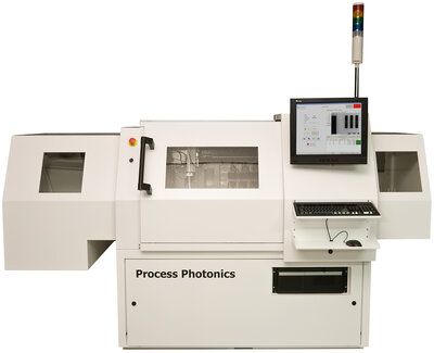
Process Photonics is an Ottawa, Ontario-based company that builds processing systems for the PCB, electronics assembly, and medical device markets. Their ProVision™ series is a solution that uses vision to inspect panel and sheet-based circuit features. Bill Young, Director of Sales & Marketing at Process Photonics explains that, "The system concept was devised after a customer expressed interest in replacing multiple existing inspection machines. This customer wanted a unit that was capable of significantly higher resolution and throughput, but also wanted to plan for a system that could perform defect recognition tasks beyond the original system's capabilities."
ProVision systems combine vision with integrated material handling automation for high-volume production. With multiple cameras operating in parallel, ProVision acquires images at a resolution better than 5 microns and implements algorithms to make highly precise and accurate measurements. The machine architecture allows for real-time image acquisition, processing, and analysis of multiple parameters per object, at over 60 parts per second. The system is scalable to higher resolution and throughput.
The system
ProVision's components include:
-
PPI Linear XY motion stages
-
5 Dalsa Piranha HS-40-04k40 cameras
-
3 Matrox Odyssey XCL vision processor cards
-
Schneider lenses
-
Gardasoft Vision PP861 LED Lighting Controller controls 5 CCS UV LEDs
-
USAF 1951 calibration targets
-
Automatic pick and place sheet loader, that puts sheets onto a vacuum platen
-
WAGO Ethernet IO controller
-
Datalogic barcode scanner
-
Aerotech motion controller
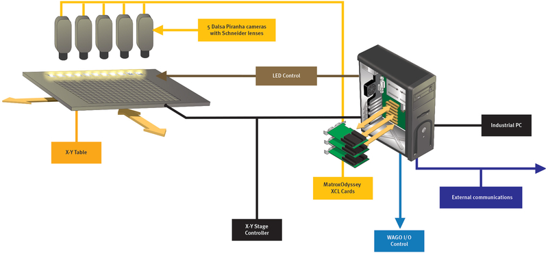
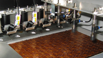
Screen-printed medical sensors are arranged on the sheet in 20 columns and 40 rows. The five bi-directional TDI line-scan cameras are spaced 4 columns apart. The sheet is scanned in 4 passes, so the first camera sees columns 1, 2, 3, 4, the second camera sees 5, 6, 7, 8, and so on. The odd numbered columns are scanned from top to bottom, and the even numbered columns are scanned from bottom to top. The three Matrox Odyssey XCL vision processors are connected to cameras 1 and 2, 3 and 4, and camera 5 respectively. At the sheet's Y axis, an encoder provides a quadrature signal through a custom-designed circuit that triggers each Matrox Odyssey XCL to acquire a line every 5.1mm.
At the start of each scan, the Matrox Odyssey XCL boards begin grabbing small frames into a circular buffer. Every time one of these buffers is filled, a call-back function copies a portion of the image into another buffer - one that is large enough to store the entire image of the sheet and wide enough to contain the ROIs (Regions of Interest). Processing threads wait until enough image data is acquired before processing the next sensor location.
At the start of the first scan, each camera locates a fiducial and measures the grayscale color of several swatches on the sheet. The fiducial location is used to adjust the sensor ROI locations, and the grayscale measurements are used for determining binarization thresholds. The image processing performs several binarization and blob analysis operations to prepare the images for the measurement operations that are performed on the sensor geometry. In order to ensure measurement accuracy, images of USAF 1951 calibration targets are acquired and measured at the start of every automated inspection task. A combination of blob analysis and marker measurement functions was used to determine the vertical and horizontal pixel scaling factors of each camera.
The acquired image data can be saved to disk for viewing; the operator can also set options and save either all sensor images or only those that have failed inspection.
The biggest challenge faced by the design engineers was how to acquire and process large amounts of data without overhead. "The engineers felt that a parallel structure was the way to go, so the Matrox Odyssey XCL boards both capture image data and process that data in parallel," says Young. Process Photonics also needed to synchronize multiple TDI linescan cameras with the motion of the parts, while the Matrox Odyssey XCL performed the image processing from each camera. The image data is acquired and processed on the Matrox Odyssey board, without needing to be transferred to the PC over the PCI bus.
Mordechai Brodt, Senior Software Engineer for Process Photonics, explains that the imaging portion of the software uses a mix of the Matrox Imaging Library (MIL) and ActiveMIL (Active X controls). The user interface is written in C# and the image analysis routines are written in C. The C code makes use of MIL threads to distribute the image analysis tasks among the Matrox Odyssey PowerPC processors. ActiveMIL was used primarily to allocate and setup the Matrox Odyssey boards, image buffers, etc.
Why Matrox?
Process Photonics has had success with Matrox Imaging products in previous systems. "The cameras generate a lot of image data, so we chose the [Matrox] Odyssey XCL to alleviate processing on the host PC," says Brodt. "Since all of the image acquisition and processing is performed by the [Matrox] Odyssey XCL, the host only coordinates the tasks and retrieves the calculated measurement data." The Matrox Odyssey XCL makes scalability easy. "With 10 cameras connected to 5 Matrox Odyssey boards we can double the process throughput, and we can do it without significant load on the host PC, and by choosing MIL as the interface to the Matrox Odyssey XCL, we will have greater flexibility with any future hardware."
Unique solution
First and foremost, ProVision offers high accuracy and image analysis capabilities for high throughput processes. Adding to this is a uniquely packaged system in a small footprint that features high accuracy XY linear motion, camera self-calibration, and complete sheet loading, unloading, and reject automation controls. Finally, ProVision's light-tight enclosure and safety interlocks meet CE and FDA CDRH standards, which are especially important when using high intensity UV illumination. "The combination of these features is not available in other products," Young says. He explains that because of Process Photonics' experience with laser-based machining systems, the team was able to design a system that met the CE and CDRH standards.
At the time of writing, two machines were delivered to a US production facility of a major global medical device manufacturer, and these units passed factory acceptance in January 2008. Young says that Process Photonics plans to expand the ProVision system's image analysis capabilities to inspect both printed circuit boards (PCB) defects and precision laser-drilled vias (holes for printed wire boards).
For more information, contact Bill Young, Director of Sales & Marketing, Process Photonics or our Media Relations team.